The Buck Converter
How a step-down converter works, and how you control it - a plain-language guide. Chapter 1 is free; sign in to continue.
Welcome
A transformer turns one AC voltage into another almost for free - no meaningful loss, just iron and copper. So here is a fair question: why can't we do the same for DC?
The honest answer is that there is no such thing as a DC transformer. You cannot put 100 V DC in and get 50 V DC out by winding wire around a core, because a transformer only responds to changing current. A steady DC current produces no changing magnetic field, so nothing is induced on the other side.
The buck converter is the workaround. It is the most common circuit in all of electronics for turning a higher DC voltage into a lower one efficiently - and "efficiently" is the whole point. You could always drop voltage with a resistor, but a resistor turns the difference into heat. A buck converter does the same job at 95 % to 98 % efficiency, wasting almost nothing.
A place you'll meet it: solar charge control
Here is a use case worth keeping in mind the whole way through. A solar panel does not produce a fixed, convenient voltage - it produces a higher voltage that wanders with sunlight and temperature, while the battery you want to charge sits at a lower, fairly fixed voltage. Something has to bridge that gap: take the panel's variable, higher voltage and step it down to exactly what the battery needs, while wasting as little of your hard-won sunlight as possible.
That something is a buck converter. It is the heart of a solar MPPT charge controller - the box between the panels and the battery in almost every off-grid or hybrid solar system.
One thing up front, so nobody feels they are missing background: solar and MPPT are not topics of this course. We only borrow the solar charge controller as a concrete picture to hang the numbers on. If the words "solar" or "MPPT" mean nothing to you, that is completely fine - read them as "the thing the buck is plugged into" and you will lose nothing. Everything you actually need is about the buck itself.
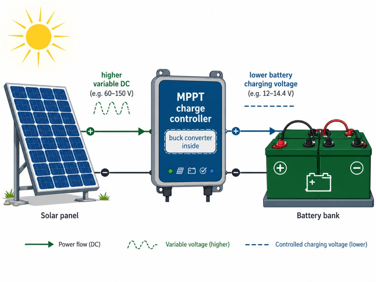
MPPT stands for maximum power-point tracking. A panel delivers the most power at one particular voltage (its "maximum power point"), which drifts with the weather. The charge controller continuously nudges its operating point to sit on that sweet spot. If you have met the boost converter doing MPPT when the panel voltage is below the battery, this is its mirror image: when the panel sits above the battery, a buck steps it down. Think of the buck as the muscle that moves power; MPPT is the brain that tells it what voltage to aim for.
We will use one realistic charge-controller operating point as the running example throughout the book - roughly a 1 kW unit charging a 48 V battery bank from a solar string. You do not need to know anything about solar to follow along; it is just a concrete place for the numbers to live.
Who this is for
This guide is for anyone who wants to understand how a buck converter works and how you control it. You need a little comfort with basic maths and some basic electronics - what voltage and current are, and roughly what a resistor, capacitor, and inductor do. That is it. Whether you come from power systems, embedded software, hardware design, or you are simply curious, you have what you need. Every time a formula appears, it is followed by a plain sentence telling you what it means.
How this course is organised
- Chapters 1-2 - How it works. Why we step DC down, the switch-and-store idea, and how the inductor and capacitor behave.
- Chapter 3 - Designing the filter. How to choose the inductor and capacitor from the ripple you will accept.
- Chapter 4 - Where the energy goes. Why a real buck is not perfect, and the shape of its efficiency curve.
- Chapters 5-8 - How you control it. Why the circuit needs feedback, how PWM turns a duty cycle into switching, a voltage controller (PI with feed-forward), and the cascade of voltage and current loops that real converters use. You write each one as a few lines of C in the simulator.
A few recurring boxes will help you navigate:
The one thing to remember from a section. If you read nothing else, read these.
A concrete example with real numbers, so the ideas don't stay abstract.
How something is actually done in commercial parts and datasheets - which is often not how the textbook does it.
A short, friendly definition of a piece of power-electronics vocabulary.
The converter we'll come back to
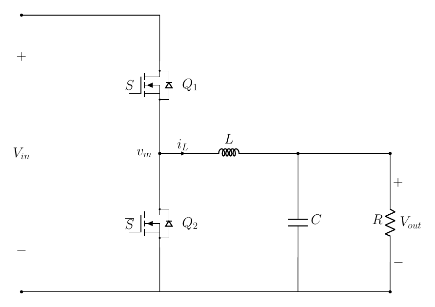
Throughout this book we use one specific buck converter, shown in Figure 1, drawn as a half-bridge: two switches, $Q_1$ on top and $Q_2$ on the bottom, stacked between the input and ground, with the inductor and capacitor forming the output filter.
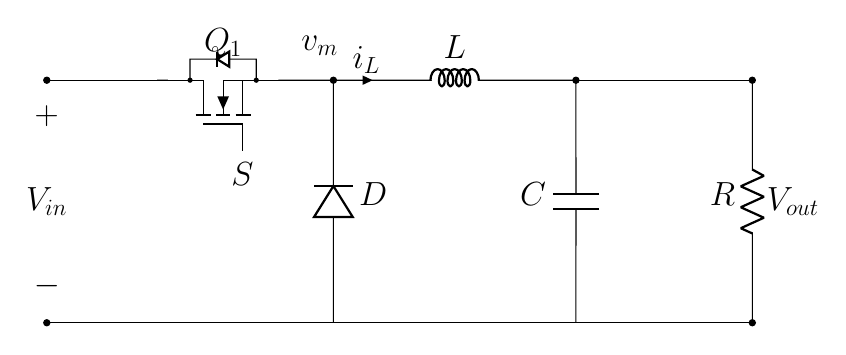
If you have seen a buck converter before, you have probably seen it drawn a little differently: with a single switch on top and a diode on the bottom. That diode version is the more common textbook picture, and the two work almost exactly the same way. We use the two-switch (half-bridge) drawing here because it makes the core idea easier to see - both switches are the same kind of device, and it is obvious how the switch node is pulled up or down. We will meet the diode version properly in Chapter 4.
The numbers we will use everywhere are collected below - a realistic operating point for a ~1 kW solar charge controller. Don't try to absorb them now; just know that whenever a worked example appears, these are the values behind it.
| Symbol | Meaning | Value |
|---|---|---|
| $V_{in}$ | Input voltage (PV string at its power point) | $100\ \mathrm{V}$ |
| $V_{out}$ | Output voltage (the 48 V battery, charging) | $50\ \mathrm{V}$ |
| $D$ | Duty cycle ($=V_{out}/V_{in}$) | $0.5$ |
| $I_{out}$ | Load (charge) current | $20\ \mathrm{A}$ |
| $P$ | Power | $\approx 1\ \mathrm{kW}$ |
| $L$ | Filter inductor | $100\ \mu\mathrm{H}$ |
| $C$ | Output capacitor | $470\ \mu\mathrm{F}$ |
| $R$ | Load (battery modelled as a resistor) | $2.5\ \Omega$ |
| $f_{sw}$ | Switching frequency | $50\ \mathrm{kHz}$ |
Why step down DC?
What a buck converter does
A buck converter takes a DC voltage in and produces a lower DC voltage out, while wasting as little energy as possible. In our running example it takes the roughly 100 V from a solar string and delivers the 50 V a 48 V battery wants while charging. Wherever a circuit needs a lower DC voltage than the supply provides, there is almost certainly a buck converter doing the conversion.
Buck is just the traditional name for a step-down converter. "Bucking" the voltage means pushing it down. Its mirror image, which steps voltage up, is the boost converter - the subject of a companion guide.
Why not just use a resistor?
If all you want is a lower voltage, the simplest idea is to put a resistor in series with the load and let it soak up the extra voltage (Figure 2). It works, and for tiny signal-level jobs it is fine. But it is hopeless for power, and it is worth seeing exactly why, because the reason is what motivates the whole buck converter.
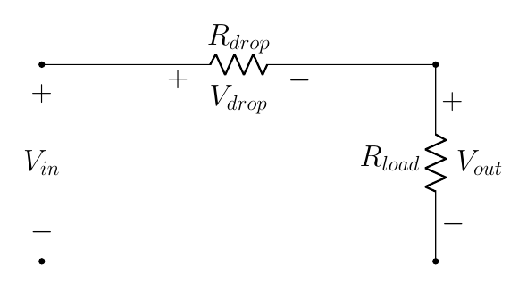
Take our solar numbers: 100 V in, and we want 50 V at the 20 A the battery is drawing. To drop the voltage with a series resistor, that resistor must carry the full 20 A while 50 V appears across it. The power it burns is
$$ P_\text{resistor} = V \times I = 50\ \text{V} \times 20\ \text{A} = 1000\ \text{W}. $$The battery receives 50 V × 20 A = 1000 W. So you would throw away a full kilowatt as heat to deliver a kilowatt - half of your hard-won solar power, gone, and the resistor glowing. And the deeper you step down, the worse it gets.
A resistor steps voltage down by destroying the unwanted energy as heat. The efficiency of a plain linear voltage drop is just $V_\text{out}/V_\text{in}$ - so it can never do better than the ratio you want. The buck converter exists to do the same voltage drop while keeping the energy.
Switching instead of dissipating
Look at the point labelled $v_m$ in Figure 3 (our converter again, repeated here so you don't have to flip back) - the node sitting between the two switches. This node is the whole secret of the buck converter, so let us watch what happens to its voltage as the switches operate.
The two switches always do the opposite of each other: when one is closed, the other is open. (They must never be closed at the same time - that would connect $V_{in}$ straight to ground through both switches, a dead short.) So at any instant there are only two possible states. Let us call the state of the top switch $S$: $S = 1$ when $Q_1$ is closed, and $S = 0$ when $Q_1$ is open.
State $S = 1$ - top switch closed. A closed (ideal) switch is just a piece of wire. So $Q_1$ becomes a wire connecting $V_{in}$ directly to $v_m$. A wire between two points forces them to the same voltage:
$$ v_m = V_{in}. $$State $S = 0$ - top switch open, bottom switch closed. Now $Q_1$ is an open gap and $Q_2$ is the wire. $Q_2$ connects $v_m$ directly to ground, so
$$ v_m = 0. $$So the switch node is never held at some in-between voltage - it is yanked all the way up to $V_{in}$ or all the way down to 0, depending only on which switch is closed. We can write both cases in one line. Since $v_m = V_{in}$ when $S = 1$ and $v_m = 0$ when $S = 0$,
$$ v_m = S \, V_{in}. $$It helps to see each state as its own circuit (below). In each one, the conducting path is drawn solid and carries the green current arrows; whatever is not part of the active circuit is greyed out and crossed off. When the top switch is closed (left), it acts as a plain wire pulling $v_m$ up to $V_{in}$, while the bottom switch is open and out of the picture. When the top switch is open (right), the input is disconnected entirely (so $V_{in}$ itself is crossed off - it no longer has a complete path), and the current instead free-wheels up through the bottom switch, which holds $v_m$ at 0.
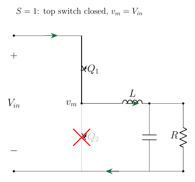
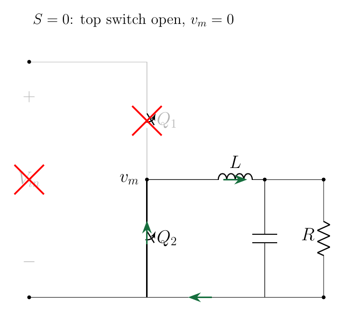
Figure 4 shows this happening. The top trace is the gate signal $S$ that drives the top switch - on, off, on, off. The bottom trace is the switch node $v_m$ it produces: every time the gate goes on, $v_m$ leaps up to $V_{in}$; every time it goes off, $v_m$ falls to 0. The switch node is just the gate signal scaled up to $V_{in}$ - exactly what $v_m = S\,V_{in}$ says.
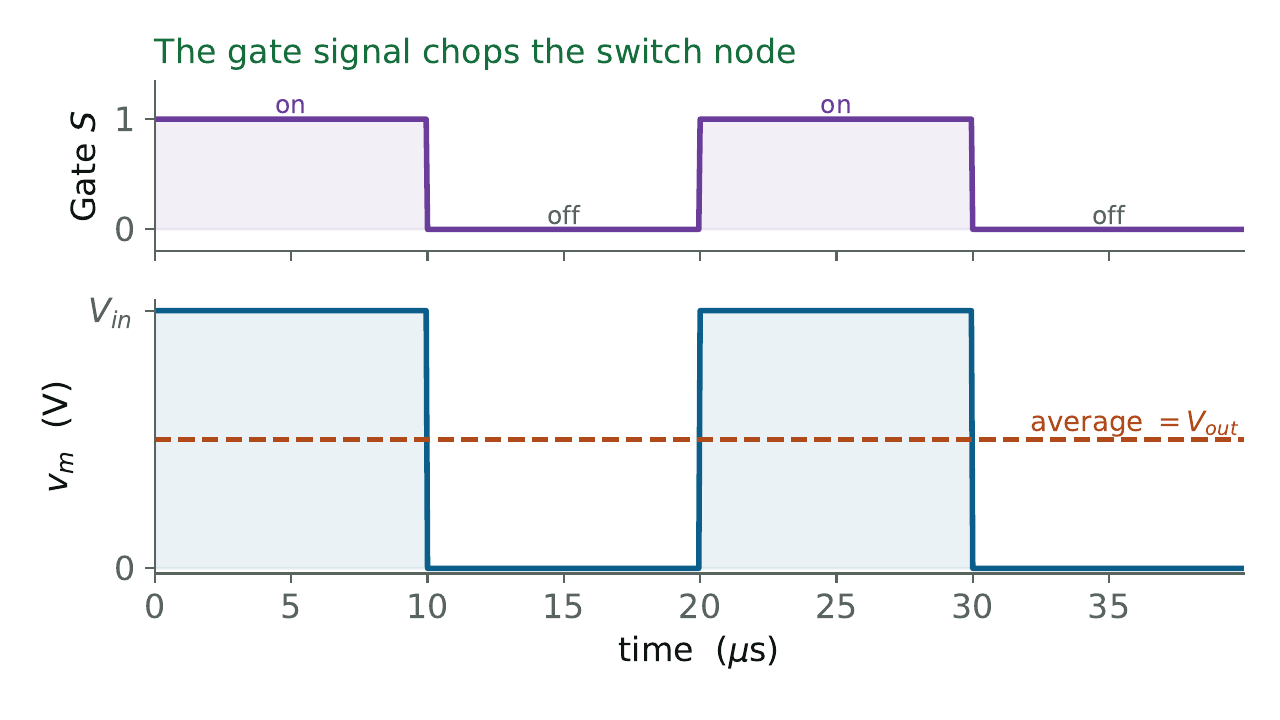
The switch node $v_m$ is a square wave: it jumps between $V_{in}$ and 0 as the switches flip, tens of thousands of times per second. The converter never holds an in-between voltage anywhere - it makes the average come out right.
The beautiful part is that this chopping wastes almost no energy. A closed ideal switch has no voltage across it (it is a wire), and an open switch carries no current - and power is voltage times current, so either way the switch itself burns essentially nothing. Unlike the resistor, which had to sit there dissipating $V_{drop} \times I$ the whole time, the switches pay almost no toll. That is the heart of it: a buck converter trades a lossy voltage drop for a lossless voltage chop.
From a square wave to a steady output
A square wave jumping between 0 and $V_{in}$ is not what the battery wants - it wants a calm, steady $V_{out}$. That is the job of the inductor $L$ and the capacitor $C$. Together they form a low-pass filter: they iron out the fast switching ripple and pass through only the slow average of whatever they are fed. (Chapters 2 and 3 open this up in detail.)
Because the filter passes the average, the output voltage is simply the average value of the switch-node square wave:
$$ V_{out} = \text{AVG}(v_m) = \text{AVG}(S\,V_{in}) = \big(\text{average of } S\big)\,V_{in}. $$The "average of $S$" is just the fraction of each cycle that the top switch is closed - and that fraction has a name: the duty cycle, $D$. Putting it together gives the single most important equation in this whole book:
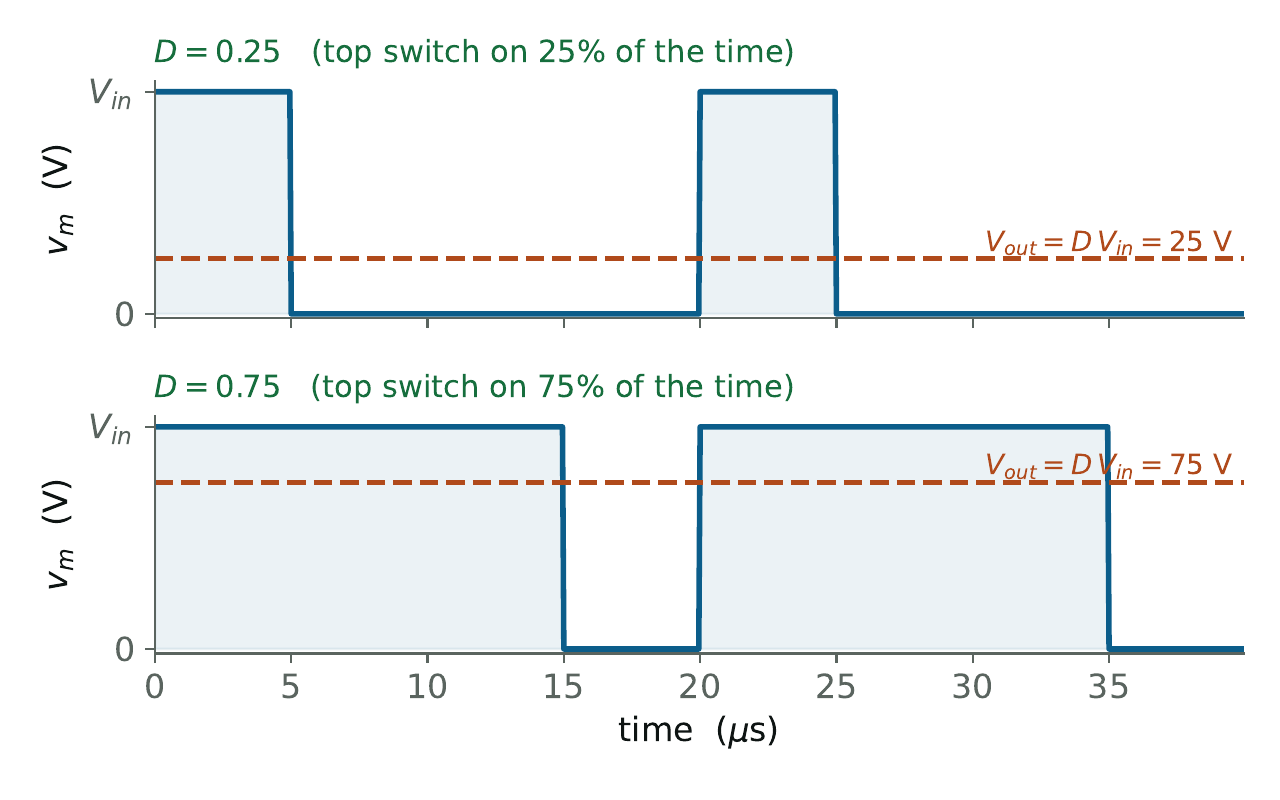
$$ \boxed{\,V_{out} = D \, V_{in}\,} $$Figure 5 shows why $D$ is the control knob. In each panel the blue trace is $v_m$ and the dashed line is its average - the voltage the battery actually feels. Keep the top switch on for only a quarter of the time ($D = 0.25$) and the average sits low; keep it on for three-quarters ($D = 0.75$) and the average rides high. Sliding $D$ between 0 and 1 slides $V_{out}$ anywhere between 0 and $V_{in}$ - exactly the lever a controller (or the MPPT brain) pulls to set the charging voltage.
The averaged model: a voltage source of $D\,V_{in}$
This last point is worth turning into a picture, because it makes a lot of what follows much easier. We have just seen that, on average, the chopped switch node behaves like a steady voltage of $D\,V_{in}$. So whenever we care about the slow behaviour - how the output settles, how it reacts to a load step, how the controller behaves - we can simply forget the chopping and replace the whole switching stage with a single voltage source equal to $D\,V_{in}$. The buck then collapses into the simple circuit below: a DC source of $D\,V_{in}$ feeding the inductor and capacitor.
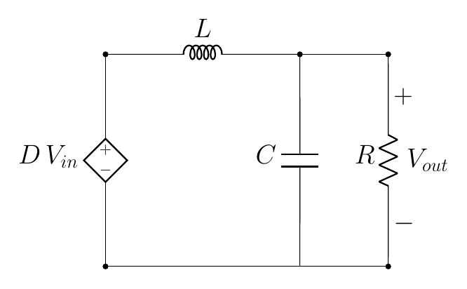
This is called the averaged model, and it is the mental picture behind the rest of the book. It also shows, at a glance, why $D$ is such a clean control knob: turning $D$ turns the source voltage $D\,V_{in}$ directly, and the output follows. We will use this picture whenever we stop caring about the individual switching cycles and start caring about the converter as a whole.
The switch node is chopped between $V_{in}$ and 0; the L-C filter averages it. So the output is the input times the fraction of time the top switch is on: $V_{out} = D\,V_{in}$. And for the slow behaviour, the whole switching stage can be replaced by a voltage source of $D\,V_{in}$ - the averaged model. Want 50 V from 100 V? Keep the top switch on half the time, $D = 0.5$. (A real inductor and the switches carry a little resistance, so in practice $V_{out}$ lands a hair below $D\,V_{in}$ - a volt or so at full load here - which is why the simulator settles a touch under 50 V. A controller trims that out completely, as we will see in the control chapters.)
Duty cycle ($D$) is the fraction of each switching cycle that the top switch is closed - a number between 0 and 1. It is the one knob a controller turns to set the output. Because $D \le 1$, the output can only ever be lower than the input: a buck only steps down. The whole control half of this book is about choosing $D$, moment to moment, to hold $V_{out}$ steady.
The bottom switch we have drawn as a transistor $Q_2$, but it is often a plain diode instead (Figure 6). The diode is less clever, but it happens to conduct automatically at exactly the moments $Q_2$ would have been closed - so it produces the same $v_m = 0$ state on its own, with no control signal. That cheaper, more famous version is the asynchronous (or diode) buck; our two-switch version is the synchronous buck. We compare them properly in Chapter 4.
That's the end of the free chapter
You have seen the headline result - $V_{out} = D\,V_{in}$ - and why a buck chops instead of drops. The rest of the course opens the box: how the inductor and capacitor behave, how to size them, where the losses go, and how to control the output with PWM, a voltage loop, and cascade control. Sign in to continue - the rest of the course is free.
Sign in to continue →