How the boost behaves
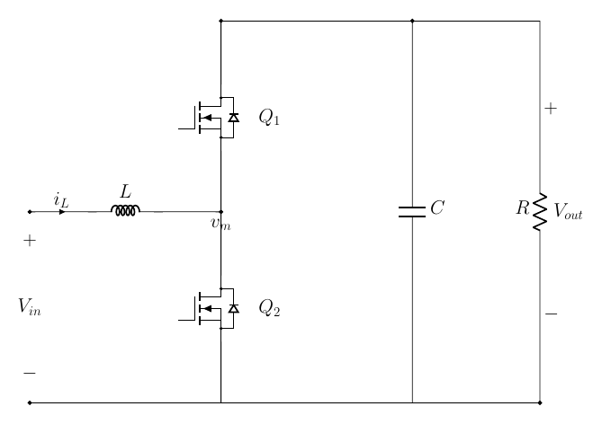
This chapter is the heart of the course. We work out how the boost's two storage elements behave - the inductor's current and the capacitor's voltage - straight from the two laws that govern them. Everything else (the averaged model, the wrong-way response, even why the capacitor must be large) falls out of these two behaviours. Here is the converter again, with its switch node $v_m$, to refer to throughout.
The inductor current
The current in an inductor is set by the voltage across it. That is the inductor's defining law,
$$ v_L = L\,\frac{di_L}{dt}, $$which says the voltage across the inductor fixes how fast its current changes: a positive voltage makes the current rise, a negative one makes it fall. So to follow the current, follow the voltage on the inductor through the two switching states (the two-state figure in Chapter 1).
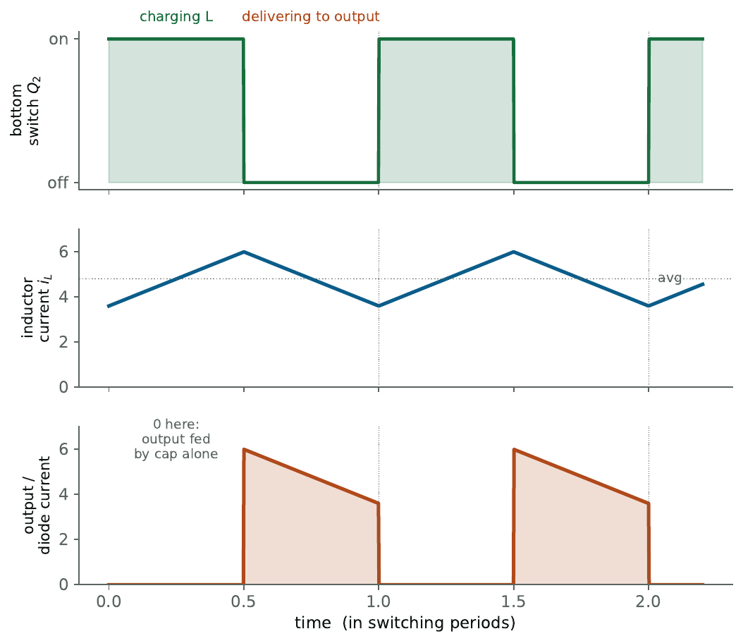
Bottom switch closed. The inductor sits straight across the input, so $v_L = V_{in}$. That is positive, so the current ramps up, at the rate $di_L/dt = V_{in}/L$.
Top switch closed. The inductor now reaches from the input up to the output, so $v_L = V_{in} - V_{out}$. Since the boost steps up, $V_{out} > V_{in}$, so this is negative and the current ramps back down.
The result is the triangular inductor current below: up while the bottom switch is on, down while the top switch is on, the same every cycle.
The output voltage
The output voltage is set by the current into the capacitor, in exactly the same way. The capacitor's defining law is
$$ i_C = C\,\frac{dv_{out}}{dt}, $$so the current flowing into the capacitor fixes how fast the output voltage changes. To follow the output voltage, follow the current at the output node.
The load draws a roughly steady current: if the output voltage is roughly constant, the resistor's current $I_{out}=V_{out}/R$ is roughly constant too. The inductor, on the other hand, only reaches the output during the off-time (top switch closed); during the on-time (bottom switch closed) the output is disconnected and the inductor delivers nothing there. Put those together at the output node:
During the off-time, the inductor delivers current to the output. It supplies the load and the surplus flows into the capacitor, so $i_C>0$ and the output voltage rises.
During the on-time, the inductor delivers nothing, so the capacitor alone supplies the load. Current flows out of the capacitor, so $i_C<0$ and the output voltage falls.
That up-and-down is the output-voltage ripple, and it is why the output current arrives in pulses rather than continuously.
The averaged model
Both behaviours - the current set by the inductor voltage, the voltage set by the capacitor current - lead straight to a simple averaged picture of the boost. Stop tracking the individual switching cycles and keep only the averages.
Take the inductor first. All it cares about is the voltage on each side. On its left is the input, $V_{in}$. On its right is the switch node, which on average sits at $v_m = (1-D)\,V_{out}$ - a voltage we set with the duty cycle. So in the averaged model the inductor simply has the input source on one side and a duty-controlled voltage source on the other.
Now the output. All it cares about is the current into the capacitor. On average the inductor delivers $(1-D)\,i_L$ to the output (it only reaches there for the fraction $1-D$ of each cycle), so the averaged model feeds the capacitor and load with that average current.
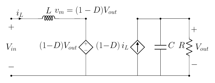
This smooth, ripple-free picture is the one the control chapters use, because it shows cleanly how the output reacts to a change in the duty. It also exposes the boost's awkward streak: the duty multiplies the output quantities, not the input, so the link between the knob ($D$) and the result ($V_{out}$) is not a straight line as it was in the buck. (As a check, set the inductor's average voltage $V_{in}-(1-D)V_{out}$ to zero and you recover $V_{out}=V_{in}/(1-D)$ from Chapter 1.)
The output dips before it rises
The same two behaviours explain the boost's most surprising trait. Suppose the controller wants more output voltage. Its only lever is the duty. To push more energy out it must first store more in the inductor - which means keeping the bottom switch on longer. But we just saw that during the on-time the output is disconnected and the capacitor alone supplies the load. So during that longer on-time the output voltage actually drops. Only once the inductor has charged up does the extra energy reach the output and lift it.
So ask a boost for more, and it first gives you less: the output moves the wrong way before the right way.
This "wrong way first" behaviour has a name - a right-half-plane (RHP) zero - but you do not need the maths behind the name, only the behaviour: ask for more and you get a momentary dip before the rise. It is built into any converter that feeds its output in pulses from a stored-energy stage (the boost, buck-boost and flyback) and cannot be designed away. A buck has no equivalent. Its one practical consequence: a boost has to be controlled gently, which shapes the next two chapters.
Sizing the inductor and capacitor
How big should $L$ and $C$ be? Their size sets how much ripple you get - on the inductor current and on the output voltage. The sizing follows the same principle as in the buck course; only the formulas change, because the boost feeds its output differently. We do not derive them here (the buck course works through component sizing in full), but here they are:
$$ \Delta i_L = \frac{V_{in}\,D}{L\,f_{sw}}, \qquad\qquad \Delta V_{out} \approx \frac{I_{out}\,D}{C\,f_{sw}}. $$A bigger inductor or a faster switching frequency means smaller current ripple; a bigger capacitor means smaller voltage ripple - the same trade-offs as the buck.
The one difference worth flagging is the capacitor: a boost generally needs a larger output capacitor than a buck of the same rating, and we have already seen why. In a buck the inductor feeds the output continuously, so the capacitor only smooths a gentle current. In a boost the output is disconnected for the whole on-time, and the capacitor alone holds the load up through it - carrying that hard, pulsed demand takes more capacitance.
The inductor current is set by the voltage across it ($v_L = L\,di_L/dt$): up while the bottom switch is on, down while the top switch is on. The output voltage is set by the current into the capacitor ($i_C = C\,dv_{out}/dt$): up when the inductor charges it, down when the cap supplies the load alone. The averaged model follows directly, and because the output is fed only in pulses the boost needs a bigger capacitor and dips the wrong way before it rises.
Controlling the boost
Up to now the duty cycle $D$ has been a knob we set by hand. In a real boost a controller turns that knob automatically, thousands of times a second, to hold the output where we want it. This short chapter says what the controller is for and the two ways to build it; the next one shows them running.
What we are controlling
The objective is simple: hold the output voltage at a chosen target $V_{ref}$, whatever the input and load do. The controller measures the output, compares it with the target to get an error, and from that error decides how to move the duty - up if the output is low, down if it is high. Some applications care about a second quantity too: the inductor current, which you may want to hold or limit (a boost's input current is the large one, so keeping it in check protects the switches). Which of those you care about decides which controller you pick.
The two controllers
There are two standard ways to do it, and the simulator has both.
Voltage control is a single loop: it watches the output voltage and sets the duty directly.
Cascade control wraps a second, faster loop inside the first: the outer loop watches the voltage and asks for a certain inductor current, and a fast inner loop makes the current follow. Here they are side by side:


The difference in one line: use voltage control when you only care about the output voltage; use cascade control when controlling or limiting the current matters too. Cascade also copes with the boost's gentleness a little better, which is why it is the industry default - but for simply holding the voltage, the single loop is enough.
Both are the same controllers as in the buck course; the principles do not change. For the full detail of how a PI loop is built and tuned, and the deeper comparison of the two, go to the buck course. Here we keep to what a boost adds.
From duty to gate signal: PWM
One link in the loop is worth a sentence, because it is the same in every converter. The controller's output is a smooth, continuous number - the duty - but the switches only understand on or off. PWM (pulse-width modulation) bridges the two: it turns the continuous duty into the on/off gate signal. It is far easier to design a controller that outputs a continuous value than one forced to speak only in on/off pulses, and PWM is what lets the controller do exactly that. The buck course shows how it works in detail.
The two controllers, and how they work
We are controlling one thing - the output voltage $V_{out}$ - with one knob, the duty cycle $d$. But the boost couples two quantities you cannot separate: the inductor current is set by the voltage across the inductor ($L\,\frac{di_L}{dt}=V_{in}-(1-d)V_{out}$), and the output voltage is set by the current the diode pushes into the capacitor ($C\,\frac{dV_{out}}{dt}=(1-d)i_L-i_{load}$). You cannot move the voltage without first moving the current. That is why every plot below shows the voltage next to the current, and it is the reason the second controller regulates the current directly.
Voltage control: one loop
The single loop measures $V_{out}$, takes the error $e = V_{ref}-V_{out}$, and sets the duty. The boost-specific trick is a feed-forward: hand the loop the duty the operating point already needs, $d_0 = 1 - V_{in}/V_{ref}$, so the PI only trims the small residual:
$$ d \;=\; \underbrace{1-\frac{V_{in}}{V_{ref}}}_{\text{feed-forward }d_0} \;+\; \underbrace{K_P\,e + K_I\!\int e\,dt}_{\text{PI trim}}, \qquad K_P = 8\times10^{-4},\; K_I = 0.6 $$The gains are deliberately tiny. A boost has a right-half-plane zero (Chapter 2): asking for more output first makes it drop, so a fast loop fights its own response and rings. The feed-forward does the heavy lifting; the gentle PI only cleans up.
Step the target from 24 V to 30 V and watch all three signals at once - this is the real simulator output, not a sketch:

Read it top to bottom and the coupling is visible: the duty moves first, the current responds, and the voltage follows the current. The output overshoots and rings because a single loop fast enough to catch the voltage is already too fast for the wrong-way zero.
Cascade control: a current loop inside
Cascade control puts a fast inner current loop inside the slow voltage loop. The outer loop no longer sets the duty directly - it sets a current reference $i_{ref}$, and the inner loop drives the inductor current to it every switching cycle:
$$ \text{outer:}\quad i_{ref} = K_{P,V}\,e_V + K_{I,V}\!\int e_V\,dt \;\;\big(\text{clamped to } I_{max}\big), \qquad e_V = V_{ref}-V_{out} $$ $$ \text{inner:}\quad d = \Big(1-\frac{V_{in}}{V_{out}}\Big) + K_{P,I}\,e_I + K_{I,I}\!\int e_I\,dt, \qquad e_I = i_{ref}-i_L $$with $K_{P,V}=1,\,K_{I,V}=80$ outside and $K_{P,I}=0.5,\,K_{I,I}=2000$ inside. The inner loop is fast (it runs every cycle); the outer loop stays slow. Because the current is now regulated, two things change: it cannot run away (you clamp $i_{ref}$ at $I_{max}$), and the outer loop drives a tamer system - a current source feeding the capacitor - so it can hold the voltage without the wild overshoot of the single loop.
Same 24 V to 30 V step, single loop against cascade, all three signals:

The middle panel is the whole argument: the single loop lets the current swing wildly, the cascade holds it. Regulating the current first is what tames the voltage.
Voltage control is one PI loop plus a feed-forward duty $d_0=1-V_{in}/V_{ref}$, kept slow because of the boost's wrong-way zero. Cascade control wraps a fast inner current loop inside it: the outer loop commands a current, the inner loop delivers it. Since the boost's voltage is set by its current, controlling the current first is what lets you control the voltage cleanly - and it limits the current for free.
In a sentence
A boost is a buck with the input and output swapped: the inductor moved to the input, the voltage ratio inverted to $V_{out}=V_{in}/(1-D)$. Its inductor current is set by the voltage across it and its output voltage by the current into the capacitor; from those two facts come the averaged model, the need for a larger capacitor, and its dip-before-rise. That dip makes a boost a little less stable than a buck - it has to be controlled more gently - which is why the cascade, with its inner current loop, is the usual choice. For the controller detail and the full component sizing, the buck guide is the companion to this one.