The Boost Converter
How a step-up converter works, and how you control it - a plain-language follow-up to the buck guide.
Welcome
The boost converter is a close cousin of the buck: the same circuit with the input and output swapped. You do not have to have read the buck guide, but you should understand how a buck converter works before starting here, because this guide builds on that understanding. A buck is the simpler of the two, and the two are so similar that knowing the buck first makes the boost easy.
That is also why this guide is shorter: it does not go through everything in the same detail as the buck guide does. You have everything you need to follow this course right here, but where you want more depth on a particular point - the full L and C sizing, how PWM works in detail, the deeper voltage-versus-cascade control comparison - the buck guide is where to find it.
Here is the plan:
- Chapter 1 - how a boost differs from a buck, physically.
- Chapter 2 - how the boost behaves: its inductor current, its output voltage, and the averaged model.
- Chapter 3 - the control objectives and the two controllers you can use.
- Chapter 4 - the two controllers in action, compared with the buck.
The companion boost simulator runs alongside the text, and the Try it in the simulator boxes point you to the exact experiment each time.
The converter we'll come back to
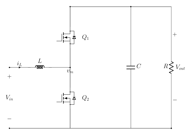
We will use one specific solar-to-battery boost throughout, matched to the companion boost simulator so that every number here is one you can reproduce on screen. A solar panel sitting at about 12 V feeds the boost, which lifts it to charge a 24 V battery - a clean two-times step-up, the mirror of the buck guide's two-times step-down.
| Symbol | Meaning | Value in this guide |
|---|---|---|
| $V_{in}$ | Solar-panel voltage (the lower source) | $12\ \mathrm{V}$ |
| $V_{out}$ | Battery voltage (the higher bus) | $24\ \mathrm{V}$ |
| $D$ | Duty cycle ($=1-V_{in}/V_{out}$) | $0.5$ |
| $I_{out}$ | Battery charging current | $2.4\ \mathrm{A}$ |
| $I_{in}$ | Panel current ($\approx P/V_{in}$) | $\approx 4.8\ \mathrm{A}$ |
| $P$ | Power | $\approx 58\ \mathrm{W}$ |
| $L$ | Inductor | $100\ \mu\mathrm{H}$ |
| $C$ | Output capacitor | $100\ \mu\mathrm{F}$ |
| $R$ | Battery (modelled as a resistor) | $10\ \Omega$ |
| $f_{sw}$ | Switching frequency | $100\ \mathrm{kHz}$ |
Notice one thing already: the panel (input) current is larger than the battery's charging (output) current. Power in equals power out, and the panel voltage is lower, so the input side must carry more amps. That is the reverse of the buck, and it matters later.
How a boost differs from a buck
The boost and the buck are built from the very same parts: two switches, an inductor, and an output capacitor feeding a load. The whole difference is where the parts are connected.
The same circuit, input and output swapped
Here are the two converters side by side, drawn to the same scale.
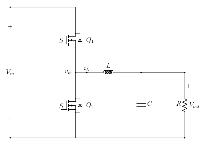
In the buck, the input feeds the top of the half-bridge and the inductor carries power out to the load. In the boost, the inductor sits on the input side, feeding the switch node, and the output is taken from the top rail. The two switches are the same devices doing the same job of pulling the switch node up or down. We have simply turned the circuit around and pushed power the other way through it.
A boost is a buck with the input and output swapped. Same two switches, same inductor, same output capacitor and load - the inductor has just moved to the input side. Everything you learned about the switches, dead-time and PWM carries straight over.
The duty cycle and the voltage ratio
Recall the buck. Its two switches are complementary, and we defined the duty cycle $D$ as the fraction of the time the top switch is closed; the output came out as $V_{out} = D\,V_{in}$.
Keep that exact same definition and apply it to the boost. Nothing about the gate signals changes - it is the same half-bridge driven the same way - only where the output is connected. Working through the switch node (the boost's top switch connects it to the output), the result is:
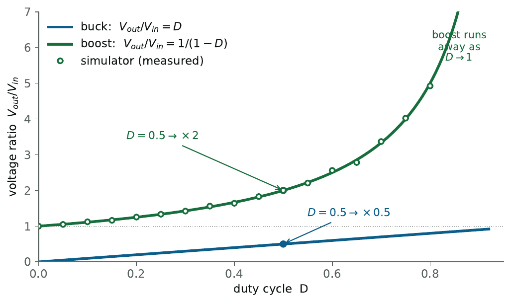
$$ \text{buck: } V_{out} = D\,V_{in}, \qquad\qquad \text{boost: } V_{out} = \frac{V_{in}}{D}. $$They are reciprocals. With the same gate timing, the buck multiplies the input by $D$ and the boost divides by $D$. The familiar boost formula $V_{out} = V_{in}/(1-D)$ is the very same thing, just written with the duty of the bottom switch (the one a boost actively drives), which is $1-D$.
The duty cycle is the same gate timing in both. Read off the top switch, the buck multiplies the input by $D$ and the boost divides by $D$. The boost's "$1-D$" only appears because a boost names its duty after the bottom switch it drives.
How the boost steps up
Why does swapping the ends lift the voltage? Follow the inductor through the two states, set by which switch is closed (the green loops below).
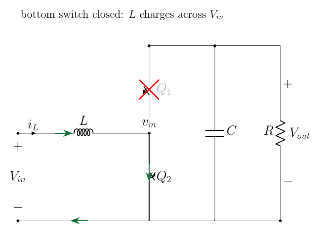
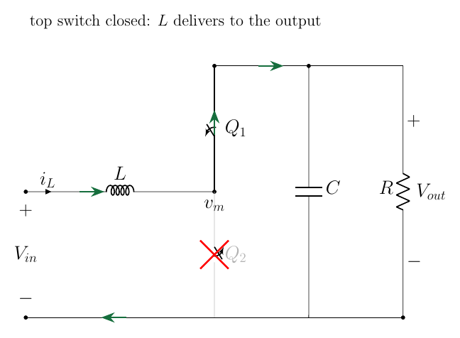
Bottom switch closed (left). The inductor is connected straight across the input, so it sees the full $V_{in}$, its current ramps up, and it stores energy. The output is disconnected from the inductor, and the load is held up by the capacitor alone.
Top switch closed (right). The inductor will not let its current stop, so it keeps pushing toward the output, developing whatever voltage it must on top of the input. Input plus the inductor's push add in series, so the output sits above the input.
So a boost stores energy while the output is disconnected, then releases it in series with the input - pumping a packet of energy up the hill each cycle. That is the whole step-up mechanism, and it is also why the output current is delivered in pulses (only during the second state), a point that comes back when we size the capacitor.
The diode (asynchronous) version
Just like the buck, a boost can also be built with a diode in place of the top switch - the asynchronous boost, below. The bottom switch is still actively driven; the top one becomes a diode that lets current flow out to the load by itself.
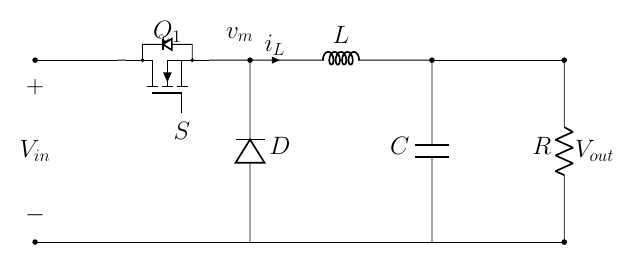
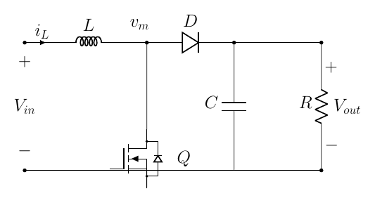
The trade-off is a familiar one. The diode is cheaper and needs no gate-drive signal, but it drops a fixed forward voltage and so wastes more power, and it only passes current one way - so the converter cannot run backwards. The second active switch costs more and has to be driven, but it conducts with very little loss and lets power flow either direction. Throughout the rest of this guide we use the two-switch (half-bridge) version, because a half-bridge is more intuitive to reason about than a diode: both switches are things you actively drive, so it is clear at every instant which one is on and where the current goes.
A boost is the buck turned around: same parts, input and output swapped, voltage ratio inverted ($\div D$ instead of $\times D$). It can be built with two switches or with a switch and a diode, exactly like the buck. What is genuinely new is in the next two chapters.
Sign in to continue
Chapter 1 is free. Sign in to read the rest of the course - how the boost behaves, the averaged model, the wrong-way response, and the two controllers in action.
Sign in to continue